Subaru WRX Forum banner

Clock pod mod with Subarb Select Monitor ECU polling and Arduino

99K views 187 replies 27 participants last post by  adri2760  
#1 · (Edited)
Clock pod mod with Subaru Select Monitor ECU polling and Arduino

The check engine light: what does it mean!?!
I check my engine often; it is always in the same place. Go away, stupid light.
Image

As my car continues to age ungracefully, I am seeing this light come on with increasing frequency. When I’m out driving I don’t necessarily have my laptop on me and a car parts store may not be nearby- a quick code check is not available. Should I have my car towed for what has lately been a P0420?
I don’t think so.
Thus, I have been motivated to integrate the simple CEL code-reading functionality of learning view into my car.
But why stop there: if I am going to be communicating with the ECU to pull the codes, why not build a sensor/memory polling mechanism too?
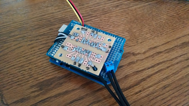
Thus, my project is a simple LCD display, powered by an Arduino Uno which communicates over the OBD II connection using the Subaru Select Monitor (SSM) protocol.


The plan for the end product is to
-Integrate with the car’s design in an unobtrusive manner: in the clock pod
-replicate the original function of the clock pod: display the time
- monitor a few interesting parameters:

1) intake air temperature: I chose this since my car, unlike many new cars, does not have an exterior temperature thermometer
2) Injector duty cycle: I have been having fuel learning issues, so I want to know if I’m reaching into the upper ranges of my injectors. Plus this is a pseudo-measure of in-use power.
3) boost: my car came without a boost gauge.
-read and display check engine light codes when the light is on in the dash display.
Image

This thread is a documentation of the development process rather than a tutorial; however I do intend to include all of the details which would enable anyone else to replicate this mod.
 
#2 ·
Integration with the Car

I want this mod to look nice (note: this doesn’t mean that I’m going to do a clean job, but the intention is good). The stock clock pod is an excellent size to fit a small LCD.
Image

Image

I chose to use the Sparkfun Serial LCD Kit because the size of the LCD almost perfectly fits into the opening.
I trimmed slots for the PCB to fit into, careful to maintain the clips for the original clock pod in case I ever want to revert, and twist tied the LCD in place. I also made a simple bezel with paint and some plastic packaging, and placed this in front of the LCD.
Image

One more thing: since the clock pod face plate was very well attached (I used much more force removing this clipped in piece than I would have liked), I trimmed the points off of the front clips using a hack saw (they still clip, but not quite as difficult to remove now).
I installed the Arduino (with the custom shield, more on this below) and LCD into the clock area by running the USB cable down to the 12V power port (to power the arduino), running a wire down to the OBD II port (for signal), and connecting a lead to the ACC (+12V) line of the clock power dongle (as a signal pull-up line).
I just closed the cover over this, leaving the parts to slide around- after all, what is one more rattle?
Image

Although the Arduino UNO can be powered with anywhere between 5-19V (i.e., it could be powered through the clock dongle), I chose to power it though USB by splicing a 12V to USB adapter into the 12V power/cig lighter. I chose this route so that I could program the Arduino (this is done over USB) by simply lifting the shifter boot and pulling out the USB cable.
Image


As a temporary solution, I spliced a line into the OBD II K-line (ISO 9141-2 comms) thinking that this would allow for simple communications. It turns out that the communications don’t work without problems yet: I need to have my VAG-Com cable plugged in or else the communications won’t work. This means that my circuit is not finished.
Image
 
#3 · (Edited)
Hardware

I found a few references which show that SSM uses a version of ISO 9141 communication- hence it shares data send and receive on a single line, serial communications (UART) at 4800 baud. It communicates at 12V, but the Arduino communicates at 5V.
Although the Arduino has libraries built in which allow for serial communication, it is designed with separate transmission (Tx) and receive (Rx) lines. These lines idle with high voltage, and pull low to signal. In order to share them, and to communicate at 12V I’ve designed a simple circuit:
Image

I use the 12V from the ACC pin in the clock pod as an OBD signal pull up, 5V from the arduino as voltage pull up for the transistors, and I use the ground in the arduino as well as an extra connection to the ground wire in the clock pod harness.

Currently, I’m using the software serial library in order to have multiple serial ports on the Arduino- this enables me to use separate serial communication to command the LCD, to troubleshoot with the Serial monitor in the Arduino (as well as program the Arduino without unplugging it) and to run the SSM communications.

I also purchased a simple real time clock kit from digispark. It communicates using the I2C bus on the arduino, and is a simple solution which allows me to keep track of time, even when power is removed (+1: now I don't lose time when the battery is pulled; -1: now I have to use a laptop to set the time on the clock in the car).

A note on soldering: it seems that my messy soldering (lots of flux everywhere) creates rather dirty circuits which can drastically affect the performance of the communication or of the crystal on the clock module. I washed the circuit with soapy toothbrush scrubbing so that everything worked.

This is all fine for now, but the SSM communications only work in short bursts (I can only send a few hundred packets before there are reading mistakes): I suspect that there is some kind of extra capacitance in this circuit which causes a delay in voltage recovery, but have not tried to confirm this hypothesis. This is not a crippling problem, since I can just pause between each data point request.
 
#4 · (Edited)
Communication – reverse engineering the reverse engineered software

Before taking on this project, I knew nothing about serial communication. I tried to find tutorials on teh interwebs, but I didn’t easily find anything. Even on the romraider forums. Thus, I sought to intercept the packets which the romraider logger and learning view sent out when it was trying to communicate with the car. This way, I could at least try and send the same packets.
My first stroke of luck was the log file which learning view leaves: it showed the ECU init packet as well as the response (and even the packet which needs to be sent to read CELs):
WRITE 6 bytes: 80 10 F0 01 BF 40
READ 68 bytes: 80 10 F0 01 BF 40 80 F0 10 39 FF A2 10 0F 3E 14 48 40 06 73 FA EB A2 2B C1 02 AA 00 10 00 60 CE 54 F8 B1 E4 80 00 E0 00 00 00 00 00 DC 00 00 45 1F 00 00 02 00 00 00 03 00 00 E0 00 00 00 00 00 00 00 00 8F
ECU supported (ECUID:3E14484006 CALID:A4TF800F DESC:05 USDM Impreza WRX MT)
Thus, I connected the Arduino to the K-line (pin 7) of the vag com cable, and powered it (line 16) and tried to pretend that the Arduino was the ECU:
Image

I even spoofed the ECU response, and was able to get learning view to communicate with the Arduino.
I took another step, and was able to read packets from romraider (now as decimals instead of hexadecimal bytes:
IAT: 128 16 240 8 168 0 0 0 18 0 0 100 166
IDC: 128 16 240 14 168 0 0 0 32 0 0 14 0 0 15 0 0 100 215
Boost (manifold relative pressure direct): 128 16 240 11 168 0 2 24 32 2 24 33 0 0 100 12

As it turns out, the logger definitions show these addresses, and how to convert them to numbers:
<parameter id="P11" name="Intake Air Temperature" desc="P11" ecubyteindex="9" ecubit="5" target="1">
<address>0x000012</address>
<conversions>
<conversion units="C" expr="x-40" format="0" gauge_min="-20" gauge_max="60" gauge_step="10" />
<conversion units="F" expr="32+9*(x-40)/5" format="0" gauge_min="0" gauge_max="140" gauge_step="20" />
</conversions>
</parameter>
This shows that (hex) 0x000012, or (dec) 0 0 18 is the address for the IAT. The byte (decimal) returned should have 40 subtracted from it in order to give the IAT in Celcius.

My circuit is even able to eavesdrop on the response from the ECU when installed in the car:
Romraider request for IAT: 128 16 240 5 168 0 0 0 18 63
ECU response: 128 240 16 2 232 84 190
That gives 84 – 40 = 44 C as the intake temperature (a tad hot, but this was after a long drive and the engine bay had a bit of heatsoak).

I’ve used this process to design the packet I sent to ask for the IAT, Manifold relative pressure (MRP), the injector duty cycle (IDC), and the CEL light status:
It turns out that IAT requests one address, IDC requests 3 (two for engine speed, one for the injector pulse width that includes the latency), MRP requests two (manifold pressure and atmos pressure), and the CEL status requests one value.
ECU poll: 128 16 240 23 168 0 2 24 32 2 24 33 0 0 18 0 0 32 0 0 14 0 0 15 0 1 150 154
Bytes Translated: [begin packet, to ECU, from diagnostics tool, 23 bytes of data, A8- the read single address byte, set to 1 for fast polling, MRP, MRP, MRP, MRP, MRP, MRP, IAT, IAT, IAT, IDC, IDC, IDC, IDC, IDC, IDC, IDC, IDC, IDC, CEL, CEL, CEL, checksum]
 
#5 · (Edited)
Programming

This is an unpolished version (no clean up of unclever/messy code, but it works as intended). It turns out that the limited memory in the Arduino UNO is a bit of a hinderance. In order to overcome this, I’ve attempted to use program memory to store the CEL character strings. Further, I’ve borrowed some code which should enable me to watch how much RAM of the 2K I have free during the run (large arrays and many variables can eat this up fast).

Also, Thank goodness for the romraider logger definitions and that community, since they've already answered many of my issues through their development.

Updated: 2014-07-26

https://drive.google.com/file/d/0ByGxElIxzv3dMG5LLUVnY0o2RWs/edit?usp=sharing

https://drive.google.com/file/d/0ByGxElIxzv3dek9PaHZOMl9PNjg/edit?usp=sharing
 
#6 ·
Troubleshooting the circuit

I'm surprise that I've received no response for this post; I'm proud to have been able to come even this far on this project.

That's not to say that there are not better implementations of a similar idea: RomRaider • View topic - Arduino Based SSM Gauge

Anyhow, I was looking at the cables in the OBD II port of my car, as well as the circuit in the Vag Com cable to see if I could understand why the cable allowed my circuit to communicate with the car.

Image


I noticed that not all of the cables are hooked up. In fact, although I had previously realized that the vag com cable could communicate with pin 7 or pin 15 (they seemed to send and receive the same bytes), the OBD port in the car does not have a connection with pin 15!. By looking at the two circuits, I can conclude that the power, ground and pin 7 are all that are involved in the communication.

This means that I have narrowed down my sources of error:
1) Perhaps my V+ in the clock pod is not correct, or maybe the pullup should be at the OBD port (the vag com cable effectively does this)
2) perhaps my ground at the cigarette lighter is not the same ground as the ECU/OBD comms (not much of a chance of this, but the cable provides a common ground between them)
3) There is still a chance that the comparator circuit is active in the communication.

I can test these ideas with a multimeter. I will report back.
 
#48 ·
I'm surprise that I've received no response for this post; I'm proud to have been able to come even this far on this project.

That's not to say that there are not better implementations of a similar idea: RomRaider • View topic - Arduino Based SSM Gauge

Anyhow, I was looking at the cables in the OBD II port of my car, as well as the circuit in the Vag Com cable to see if I could understand why the cable allowed my circuit to communicate with the car.

Image


I noticed that not all of the cables are hooked up. In fact, although I had previously realized that the vag com cable could communicate with pin 7 or pin 15 (they seemed to send and receive the same bytes), the OBD port in the car does not have a connection with pin 15!. By looking at the two circuits, I can conclude that the power, ground and pin 7 are all that are involved in the communication.

This means that I have narrowed down my sources of error:
1) Perhaps my V+ in the clock pod is not correct, or maybe the pullup should be at the OBD port (the vag com cable effectively does this)
2) perhaps my ground at the cigarette lighter is not the same ground as the ECU/OBD comms (not much of a chance of this, but the cable provides a common ground between them)
3) There is still a chance that the comparator circuit is active in the communication.

I can test these ideas with a multimeter. I will report back.
Hi
Good day
firstly : Excuse me my english is bad
Do you sure this diagram of Vag Com cable is trusted and ok ?
i think ths diagram is damage ecu Because this schematic


R2 is the pull up to 12-15v. that is unsafe.
the pull up needs to go to 5v. max.
id not exceed , TTL levels into any ECU
 
#8 ·
Alright, I finally got around to checking the OBD II port with a multimeter and here's what I found:

V+ (pin 16) is 12.XX V=battery voltage above ground (pin 4/5) and pin 4/5 matches chassis ground (why wouldn't it). No big surprises here. I measured Pin 7 vs 4/5 and got 6.XXV, and vs pin 16 and got -5.XX V, but I still had the arduino signaling turned on. When adruino signaling is disabled, I get -0.23 V vs pin 16 and 11.88 V vs gnd. (this means that the signaling is reaching the OBD port just fine, I believe)

Placing a 1 kOhm or 10 kOhm resistor as a jump (pull-up) between 4 and 7 or 16 and 7 does not enable the communication to pass through, so it appears that the comparator is active rather than a voltage drop over the signal line causing the failure in communication.

Also, I double checked the VAG com cable, and the only chip in it which is powered via OBD is the comparator (the FTDI chip is powered via USB). Ugh.
 
#9 ·
Alright, so I figured out my communication issue: one of my transistors was leaking current. At first I thought it was my shoddy soldering, so I took apart my circuit, and put it back together on another PCB.

Image


This didn't fix things, and I eventually found the bad transistor.

Image


Now, I've re-installed the arduino and it communicates without any issues. I've even got the CEL reader to work.

The Boost/IDC gauge is not the fastest (there is a lag of a couple hundred milliseconds between my input to the car and the gauge displaying the response), but it does what I need it to.

I've updated the code above.

For future plans, I may end up adding a mechanism so that I won't have to unplug it to use the OBD port. I may also change to fast polling to try and increase the response time.

The potential for using an arduino in the car is fantastic: I've seen implementations where the cruise control stalk on the steering wheel is used to select different logging parameters, and one could even write an interpretation code to use romraider's logger definitions so that this would not have to be inputted manually. In any case, I'm quite pleased with the result so far.
 
#10 ·
Good job! This looks very interesting. I like the display on the new wrx and fxt, wish my 14 would display simple things like boost, coolant temp etc.

Sent from my SAMSUNG-SGH-I747 using Tapatalk
 
#11 · (Edited)
Alright! I guess that my project was not done.

I had designed the code so that whenever the CEL came on, the code would stop polling the ECU for data parameters and instead ask once for CEL codes based upon this line in the romraider logger def. v253:

<switch id="S155" name="Malfunction Indicator Light (MIL) ON Flag" desc="S155" byte="0x000196" bit="7" ecubyteindex="56" target="1" />

I asked for the memory address 0x000196, looked at bit 7 of the response, and if that bit was 1, I would consider the CEL on.

Code:
MILbyte = bitRead(MILbyte,7); //the 7th bit of this address byte indicates whether the MIL is on
Well, I finally cleared my CEL and found that the arduino acted as if there was still a CEL. This means that this memory address is not an indication of whether or not I have a CEL and my code fails because of it. Either that or the bit index is off (if romraider counts starting at 1 and not 0, like bitRead) and I am asking about the 8th bit instead of the 7th. I'll have to give this a try.

I then went to the Romraider page to find an updated logger definition, v263.
In v253, the only mention of "MIL" (in the context of the MIL on, not mile) was in the line I posted above. In v263, there is more, so this is a developing part of romraider. I need to restructure my code. Maybe I'll change it to 1) ask for CEL codes only upon startup, 2) ask for the air temperature every 1000 poll points (so that the boost and IDC parameters are read faster).

edit: some romraider logger defns. ask for a "bit = 0" thus I do not expect that my problem is from an indexing mismatch.
 
#12 ·
ECU communication and display latency

Since I have to re-write to accommodate my inability to ask the ECU if the CEL is on, I would like to address the delay that the gauge has.

I have come up with three major sources of delay, and will focus upon reducing two of them which are based upon serial comms. timing.

1) Communicating with the LCD at 9600 baud
2) Communicating with the ECU at 4800 baud
3) Code inefficiency in math and algorithm

The code originally polled the ECU each time it wanted a data point, and received a response. Then, it updated the parameters and displayed them on the LCD.

I was polling the ECU for three parameters using seven addresses of three bytes each. Including the packet header, this is 28 bytes sent. The ECU would then respond with 13 bytes. Thus, each round trip parameter update took at least : (28+13)(bytes)*8(bits/byte)/4800(bits/s) = 68 ms.

I had set the LCD to communicate at 9600 bits/sec using 8 bit bytes. Each time the LCD was updated included sending commands to move a cursor around, to display the data and to input special characters. I have not calculated the exact number of bytes sent, but I can assume it is not too many more than a full byte for each location on the LCD (32). Thus, I expect a full refresh of the LCD to take about 27 ms. This is about 37.5 Hz, just faster than a 30 fps perception limit.

These processes happen in series, so their times are additive: 27 + 68 -> 95 ms/update, or about 10 frames per sec, which is easily perceived as a delay (not even counting the inefficiencies in programming).

Here is how I intend to reduce the delay:
1) shorten the number of polling bytes
2) increase LCD communication speed

Since I cannot figure out how to ask the ECU if the MIL is on, I will not even poll for that address. Additionally, I don't need to update the intake air temperature every cycle (since it is pretty constant over minutes), so I won't poll it every cycle either. This means I can reduce the number of bytes sent and received per cycle to about 33, giving a round trip time of 55 ms. This is still a bit slow, so I can enable fast polling mode by sending a "1" beore asking for addresses. This will make the ECU continue to send the response to the initial poll without having to keep asking. This reduces the number of bytes to 11, and the update time to 18 ms. That is about 54 Hz.

The LCD communications can be sped up by changing the serial comms speed; since the LCD and arduino are adjustable, I'm not limited (as I am with the requirement for SSM to have 4800 baud). I can change the baud rate to 57600 bits/s to get a full LCD refresh time down to 4.5 ms, or about 225 Hz.

Combined, I expect these enhancements to reduce the full cycle response time from 95 ms to 22 ms, or 43 Hz, well into a range where it will appear a fluid refresh. Assuming that my programming is not poor and that the arduino can keep up with the constant feedout of data from the ECU, hopefully this will all work out.
 
#13 ·
Very interesting. I had the same idea as you for this project, but you've taken it much farther than I ever did. I ended up using my arduino and LCD as the brains for a pachinko machine. :p
 
#14 ·
I remember seeing your post about your plan for this idea; if you're still interested you could always do something like it in the outback, since romraider has some outback ECU definitions and since the arduino is pretty cheap. It's been a fun project!
 
#15 · (Edited)
Slightly faster polling

updated code: https://drive.google.com/file/d/0ByGxElIxzv3dbE5xbm5FR2ZYNm8/edit?usp=sharing

edit: link to real time clock library, which is necessary for this code to work: https://github.com/adafruit/RTClib

Well, it turns out that my expectation about how long it takes the code to run was way off. I used arduino's timing functions to estimate the time it takes for a full polling cycle.

254 ms/cycle: My original code
194 ms/cycle: When I switched the LCD to 57600 baud
86 ms/cycle: above+ switching to the fast polling
181 ms/cycle: no fast polling, but shorter data packets
77 ms/cycle: above+ diagnostic serial at 57600 baud instead of 9600
68 ms/cycle: above+but further shorten the packet so IAT is only polled every 60s

This shows me three things:
1) I underestimated the time that the LCD refresh takes (shortening it gained me 60 ms)
2) I underestimated the time that the Serial diagnostics comms takes, thus by measuring the system I am influencing it (shortening it gained me about 100 ms)
3) Although fast polling drastically reduces the cycle time, something about my setup causes loss of accurate byte transmission after about 5 read cycles (I suspect that the resistors are not right and the voltage cannot recover, hence data bytes are incorrectly read)

In any case, I now have a v2 of the code; here are the changes:
1) Reduced cycle time (increased temporal resolution for IDC and MRP, reduced for IAT)
2) Included 20 new start up messages and 3 animations
3) CEL codes are polled at startup and not at any other time
 
#16 ·
I've been lurking this post for awhile. I'm much more active on NASIOC, as most of my DIY and mods are over there. You initially spliced into the the K-Line, but ended up doing something else. Did splicing go successfully or are you still tapping through the front OBD II port?

I looked through your code and it looks good. It could use some optimization. It seems to me like you're burning a lot of procession power running unnecessary comparisons and that loop within a loop.

Example: You're making two checks here, which it should only need to be one, case switching would be good or even just nested if-else.
If MILread is false, it'll never hit into MILread is true, so why waste processing power checking?
if(MILread == false) {
......
}
if(MILon == true && MILread == true) {
............
}


I've noticed that there was a person with 08+ WRX running a similar set up and showed off on youtube, but i can't seem to find it now. They took it off the web?

I'd love to help. Let me know what you'd need.
 
#17 · (Edited)
You initially spliced into the the K-Line, [...] Did splicing go successfully or are you still tapping through the front OBD II port?
After "fixing" my circuit (which allowed me to share the tx/rx lines while having the arduino end at 5V, OBD end at 12V) by replacing a bad transistor, the single connection on the back side of the K-line seems to be all that I need to get communication. This means that I can still use the OBDII port (but have to unplug the arduino so that it does not interrupt any other communications). I will concede that my circuit is flawed since it gets garbled numbers if there is not a pause after every few hundred bytes received. I suspect that this has to do with some kind of capacitance in the circuit which arises with the pull up resistors (I use 1 kOhm on the 12V pull up, and 10 kOhm on the 5V lines), but I am not interested in re-soldering this for a 5th time. Additionally, my code does not properly read values unless there are pauses (two Serial.println() calls) in the readECU function.. I'm stumped by this as well, but am content not asking why.


I looked through your code [... ]It could use some optimization. [...]

Example: You're making two checks here, which it should only need to be one, case switching would be good or even just nested if-else.
If MILread is false, it'll never hit into MILread is true, so why waste processing power checking?
if(MILread == false) {
......
}
if(MILon == true && MILread == true) {
............
}
When I wrote the second version, I sloppily cut and pasted the old code. You have a shape eye; it does appear that the only way for MILon to be true is if MILread == true, thus I am making an unnecessary comparison every loop. If I get bored, I may try making some optimizations (or if you're interested, you're welcome to make them for me) however, I am likely blind to the problems (even the obvious ones like this) without some kind of extra help.

The loop within the loop is my dumb way of updating the time and intake air temperature only once every minute.

I've noticed that there was a person with 08+ WRX running a similar set up and showed off on youtube, but i can't seem to find it now. They took it off the web?
Perhaps this one: Ssm arduino gauge - wrx - YouTube
The best version I've seen is the Apex Spec C: http://forums.nasioc.com/forums/showthread.php?t=2238468

At this point, I have no idea what help I need. For now, it seems to be functioning "well" and fast. If my CEL comes back and I cannot easily read it, then I ought to make some changes. If you have ideas for additions to this project, or want to try something out, I'm open to trying your code or discussing suggestions.

If I get bored, in the future I may try making the boost gauge have finer pixels (someone on youtube has done this using the parts of the 16x2 subcells), and maybe make the arduino stop trying to communicate if someone else is on the OBD port.

Other ideas for future additions to this project include
1) adding button controls via the cruise control stalk (I've no idea how to go about this for now) for selection of different logging parameters
2) adding extra sensors (it would be neat to have a lateral g-gauge)
3) adding some kind of WiFi/GPS reporting so that my car tries telling a server where it is over certain time intervals (this would be an expensive project)
4) adding an RFID reader to recognize my drivers license and disable the car without it (pie in the sky idea)

I appreciate your interest in this, and would be grateful for your suggestions.
 
#18 · (Edited)
I'm a senior software engineer by day, so I love coding. If it wasn't for this thread that you started, I could have dismissed the Adruino ability to be used as a car monitoring system, so thank you.

I've been using a bluetooth Scanner + Raspberry Pi to monitor my car, but I'd love to cut out the wireless delay, as it adds a good amount delay.

I'm also starting a thread on using the adruino to set up a dual fuel system with a smart cut-off monitor. Example:
91 < 3500 RPM
e85 + 91 > 3500 RPM

This would completely solve any problem that e85 would have.

Would you be able to make a complete DIY of the whole process that you took to set this Adruino up, including a parts list? I'd love to see.
 
#19 · (Edited)
Would you be able to make a complete DIY of the whole process that you took to set this Adruino up, including a parts list? I'd love to see.
I don't think I can handle making a clean DIY, but I believe that the installation pictures in my other posts show most of the process. I also figure that the circuit could be soldered in different ways, so I'm not planning to show my poorly soldered version. One note: I ended up using pin headers to attach the parts of the serial LCD together so that I could have a better fit in the clock pod, and so that I could remove the ATmega328 part of it. The arduino pins which I use to connect to the circuit are listed in the code (2 pins each: I2C (there are sda and scl on the arduino uno); digital outputs for LCD and SSM communication).

Installation is quite straightforward:
1) open up the clock pod, remove the old clock
2) clip in wire splice points: 1 - back side of the K-line in the OBD port; 2&3 - 12V (ACC) and ground in clock pod harness; 4&5 - 12V and ground in cigarette lighter harness
3) install power converter (the cigarette lighter-to-usb) by soldering on some wire leads, connecting to 12V and gnd. Run the USB cable between the area behind the cigarette lighter and the clock pod
4) run wires from OBD K-line, 12V (clk pod) and gnd (clk pod) up to the clock pod area to attach to the arduino
5) modify the clock pod (as in my previous posts) and install the LCD; run wires to the arduino circuits: 12V is a pull up, gnd is obvious, OBD K-line is the signal line.
6) re-assemble, leaving the arduino loose in the clock pod area.

Here is a parts list (excepting wire, arduino header pins, some solderable wire clamping headers and tools which I already had):

$19.99 Arduino Uno R3 - microcenter
$4.95 USB A to B 6' cable - microcenter
$5.99 Digistump real time clock shield kit - microcenter
$3.99 Arduino prototype shield PCB (I used header pins that I already had) - microcenter
$25.99 Sparkfun serial LCD kit - microcenter
$4.99 Vivitar USB DC dual port charger - microcenter
$1.49 5 pack of 10K 1/4 W resistors - radioshack (I used 330Ohm, 1kOhm, and 10kOhm)
$3.49 pack of 15 2N2222 transistors - radioshack
$2.49 quick splice connectors, 14-18 awg - radioshack
$1.99 quick splice connectors, 18-22 awg - radioshack
----------------------------------------------------------
$78.34

Unnecessary stuff:
$2.49 another PCB to fix all of my desoldering
$5.99 desoldering bulb to help take things apart when my circuit failed (this didn't actually help much)


I'm also starting a thread on using the adruino to set up a dual fuel system with a smart cut-off monitor. Example:
91 < 3500 RPM
e85 + 91 > 3500 RPM
This is an interesting idea; do you mean that you'd use the arduino to monitor engine speed, and then add some amount of E85 based upon that reading (directly into fuel line? or inject into intake air stream?)? If so, then I assume that you'd have to be pretty comfortable with tuning the ECU so that the car would expect the different fuel (and change the amount of injected fuel rapidly). Also, could methanol or water injection into the intake airstream (as many companies sell a kit to do) give a simpler solution for knock control?

I am very interested to see this thread, so please post it here (or at least a link to your thread) on clubwrx.
 
#22 · (Edited)
I'm thinking of doing something similar, this sounds like an interesting project.

I found this kit & tutorial from SparkFun: https://learn.sparkfun.com/tutorials/obd-ii-uart-hookup-guide - the only issue is that they've discontinued their Arduino RedBoard, but that can be replaced with the part mentioned earlier in the thread the Serial LCD Kit, which basically has an arduino board attached to it, and with the FTDI board in this package you can reprogram it using the code provided on this thread.

Using this package it's a little more costly than the OP but it should be more straight forward since the OBD II UART board does a lot in terms of normalizing the voltage (i.e. you won't have to create the custom board that was mentioned at the top of the thread) and whatnot (I think? correct me if I'm wrong)

Hope this helps someone, I won't know until I've bought the parts and tried it myself which I plan on doing in the near future. I probably won't replace the existing clock unit in my car though, will probably fashion some custom molding where the cigarette adapter is

Edit: the OBD II UART board from Sparkfun also determines the protocol to use, so if you wanted to use this setup on multiple cars, it makes swapping it between cars much easier
 
#23 ·
I decided to replace the clock because it cuts time between my vision of the road and the gauge. I added the time back into the Adruino LCD. Mounting it down where the cigarette adaptor is, will add a SIGNIFICANT gap between road and gauge. I'd advise against it.
 
#27 ·
Nice work!
And great write up, this should be a sticky.
I'm really liking those options, and gauge set up.
You would honestly think with the mods and the following the WRX has they would integrate more gauge options from the factory. So if you want boost, fuel air, oil temp, just to name a few. There should be an option for stlyeized gauge clusters set up from the factory.
Love the idea great work keep us updated.
 
#28 ·
Here's an update: the original design of the OBD interfacing circuit was causing problems- the circuit held the OBD signal line at about 7.4V (instead of the appropriate 12V) even with the arduino unplugged. This somehow caused (a current draw from the ecu and) the car to pull timing (http://www.clubwrx.net/forums/gener...oting-accidents/134468969-troubleshooting-reduced-iam-increased-fuel-trims.html).

Image


I'm not sure if it had been doing this since the installation, but the IAM reduction went away when I unhooked the OBD splice. Maybe the issue was a bad transistor? or more likely the issue was related to my poor (/lack of) engineering.

Thus, I've redesigned the circuit using a comparator:

Image


I've gotten good at un-soldering and resoldering by now, and I even 3D printed a housing for the arduino so that the D-sub port could be held in place (this'll make removing the arduino easier in the future when it inevitably fails).

Here's a nice overexposed image:
Image


Image


After a drive today, the circuit did not result in pulled timing, so I think that this may fix the issue for now. As a note to anyone trying to make this work for themselves- the 1K pullup resistor value seems to be critical for the OBD line- when I used a 10K resistor the signal was very noisy.

Also, I updated the arduino IDE from 1.0.6 to 1.6.2 and found that all of my progmem variables were causing issues with the complier. Thus, I have rewritten the code and made some changes to the way that it runs: if there are 10 checksum errors within a minute, it stops trying to poll the ecu. This way, I should not have to unplug the arduino if I want to use romraider logger or learning view.

ClockPodModV3
https://drive.google.com/open?id=0ByGxElIxzv3dbHFnaUc5UkJvNTQ&authuser=0
 
#29 ·
awesome

Obeisance,

First I want to congratulate you on a seriously amazing project. Recently I have been working towards a somewhat similar goal, and I have referred back to your research more times then I could count!

I have some questions around your circuit design and serial communication with the subaru ECU in general.

Following in your footsteps, I built a board with a LM339 per your spec. With this board, I was successfully able to connect my arduino to a vag-com cable and trick FreeSSM into thinking it was a subaru ECU. Once that was done, I was able to take two arduino's with your lm339 circuits and had one play the role of ECU and the other as my data logger. Everything works great.

However, the one place I seem to be hitting a brick wall is talking to an actual Subaru ECU. When I have connected the circuit to pin 4 (ground), pin 7(k-line) and pin 16(12+), I am able to power the arduino, however I don't see any valid packets. (note for testing, I was simply trying to send the init packet[80 10 F0 01 BF 40] and see if the ECU responded). Thus far, I have not seen any valid responses.

This brings me to my question for you, other then what you detailed in your lm339 based schematic, are there any other requirements for successful arduino <-> ecu communication?

If it helps, I can post a schematic (sorry, fritzing) of my board, but other then what you have designed, the only difference is that mine has obd pin4 & pin16 powering my arduino.

Thanks again for your work on this, and posting your research. It was a great help to me.

Cheers,
Ryan
 
#30 · (Edited)
I'm not sure that I'll be of much help: I'll start at some very basic things (so if I state the obvious please excuse me).

First, in order to communicate with the car, you have to have the key in the on position. When I had trouble, I tried eavesdropping on the communication between the computer and the ECU: by putting a splice-type connector (Radioshack PN 64-036 or the like) on pin 7, I can just listen to the bus line. This way you can be sure that you're seeing something once you've jumped circuits.

As long as you're sure that you are on the same 12V (not just the 12V for Arduino power, but also the 12V pullup on pin 7 on the LM339) and ground as your communication loop, I cannot see what is wrong. Another interesting bit: in my circuitry, during my early testing I found that communication would fail without the delay added by the "Serial.println(data);" call in the packet reader.

Also, you say that you haven't seen any "valid" responses: are you seeing any response at all?

I'm excited to hear that others are using this. Are you planning on making other changes (i.e. reading other addresses, or using the ECU data as a control for some other in-car event?)? If you're willing, could you please post pictures of your implementation to encourage others who may also be interested in trying this out?
 
#31 ·
I'm not sure that I'll be of much help: I'll start at some very basic things (so if I state the obvious please excuse me).

First, in order to communicate with the car, you have to have the key in the on position. When I had trouble, I tried eavesdropping on the communication between the computer and the ECU: by putting a splice-type connector (Radioshack PN 64-036 or the like) on pin 7, I can just listen to the bus line. This way you can be sure that you're seeing something once you've jumped circuits.

As long as you're sure that you are on the same 12V (not just the 12V for Arduino power, but also the 12V pullup on pin 7 on the LM339) and ground as your communication loop, I cannot see what is wrong. Another interesting bit: in my circuitry, during my early testing I found that communication would fail without the delay added by the "Serial.println(data);" call in the packet reader.
I was thinking this would be a good next step. I'm planning to tap into pin 7 behind the connector, and route it to my arm rest where I have the rest of my gear located. I'll make the connection and try to sniff FreeSSM connected to the ECU. Even while I was doing arduino to arduino communication, I noticed the requirement of adding serial prints or delay statements to slow things down enough to allow communication.

Also, you say that you haven't seen any "valid" responses: are you seeing any response at all?
I've been able to read some data by fiddling with the ground connection. Otherwise, I just see a lot of null responses. But to be fair, I am not using all of your code as my use case is different.

I'm excited to hear that others are using this. Are you planning on making other changes (i.e. reading other addresses, or using the ECU data as a control for some other in-car event?)?
I'm also excited to be working on this. I enjoy going to the track, and as I have spent more time there, I've wanted to improve as much as possible. So I started with video, eventually I started logging telemetry data for video overlays. Re-watching the videos are free, where track time, well... that's expensive. Over the last couple of years, I've installed a Race Capture Pro, and built some (arduino based) integration to control my gopro's. The last step for me is getting some data out of the ECU directly into the RCP. While I can do this with my accessport, it's very difficult and time consuming to line the data up with the video.

My plan, build a SSM logger to signal the RCP with rpm, speed, gear, clutch switch, brake switch, coolant temp. So I will be polling different addresses then you, and because I've already maxed out my digital inputs, will be converting all of the ECU data to be read via 5v analog signal.

If you're willing, could you please post pictures of your implementation to encourage others who may also be interested in trying this out?
Absolutely. Lots of posts out there on guys doing this with PI's, but very little when it comes to Arduino. I really like the real-time operation of the arduino and it just feels like the better tool for the job. I'll start posting progress to this thread and will add pics of my board and implementation details over the next few days/weeks,
 
#32 ·
I got back on the project this weekend and tapped into the k-line above my OBDII connector.

My results are interesting for sure!

I somewhat successfully read my first metric, RPM!!!

Two interesting conditions apply.
1) The vag-com cable must be connected to the obdii port
2) Only ground and the k-line are connected to the arduino. Adding 12v+ kills communication.

This leads me to believe there is something wrong with the board I soldered up, but heck, I have no idea even where to start looking, So perhaps it's back to a bread board to double check the connections. Speaking of my breadboard, I promised some pics of my implementation, so they are below. Notice, I used the analog pin risers as my input for 12+, K-line & ground from the car, hence the reasons the pins are filed down on the bottom.
 

Attachments

#33 ·
Lets see if I follow your board correctly:

A0: 12V
A1: rx from ECU to input 3+ on LM339 (i.e. k-line connection which can pull low) - the resistor on this connection drops the voltage before the LM339, but this is not necessary here.
A2
A3: gnd
A4
A5: tx to ECU- i.e. k-line (needs to have the 12V (1kOhm) pullup resistor so that it idles high until the LM339 pulls low)


D10: rx (will give either 0 or 5V via the pullup on output 3 on LM339)
D11:tx (to input 2+ on LM339)

input 2- on LM339 is 2.5V
input 3- on LM339 is 6V

I suspect that with your current circuit, the k-line is at an undefined voltage (I've learned that the LM339 is a sink, not a source, so without a pullup on output 2, it won't hold a controlled potential) until the external OBD cable is plugged in (this has the appropriate pull up resistor). You placed the appropriate pull up resistor on output 3 for the arduino side, though.

Also, since your reference for comparator 3 is 6V, but communication fails when you connect this, I suspect that the other line (input 3+) never reaches below 6V due to the resistor on it (I have no good guess for the potential at the microchip side of this connector).

The microchip diagram that I used is here: http://www.ti.com/lit/ds/symlink/lm339-n.pdf - is this correct?

I recommend removing the 1Kohm resistor between the LM339 and A1, and using it as a pull up between output 2 and 12V. Also, I expect that the comparison voltage on input 3- could just as easily be 2.5V (5V/2) as 6V for the circuit to work (in case you don't want to potentially draw a current from the OBD 12V line to create a reference bias).

How does this seem to you?
 
#34 ·
Lets see if I follow your board correctly:

A0: 12V
A1: rx from ECU to input 3+ on LM339 (i.e. k-line connection which can pull low) - the resistor on this connection drops the voltage before the LM339, but this is not necessary here.
A2
A3: gnd
A4
A5: tx to ECU- i.e. k-line (needs to have the 12V (1kOhm) pullup resistor so that it idles high until the LM339 pulls low)


D10: rx (will give either 0 or 5V via the pullup on output 3 on LM339)
D11:tx (to input 2+ on LM339)
Not quite.

A0: 12v batt
A1: 12v batt
A2: nothing
A3: nothing
A4: nothing
A5: K-Line

Power can connect at raw, a0 or a1. ground connects on the ground pin, the only required analog pin is 5, where the k-line goes.

I suspect that with your current circuit, the k-line is at an undefined voltage (I've learned that the LM339 is a sink, not a source, so without a pullup on output 2, it won't hold a controlled potential) until the external OBD cable is plugged in (this has the appropriate pull up resistor). You placed the appropriate pull up resistor on output 3 for the arduino side, though.
I think I do have a pull up on output 2, it's connected to a 1k resistor going to the 12v source. Its not obvious the way I soldered the board. I spent some time on a schematic. I followed what I had soldered and checked this a couple times; I think it matches my board. Is the problem easier to spot this way?
 

Attachments